3D Printing
Week 7 (Tutorial)
5. The 3D printer creates the 3D object


 Step 1: Create a sphere that is 50 mm in diameter.
 Step 2: From the base of the sphere, create a new sketch. Draw a circle that is 20 mm in diameter.
 Step 3: Extrude the new circle such that it slightly protrudes out of the sphere. The protrusion will form the base of the fuse. Ensure that "New Body" is selected when extruding the part.
 Step 4: From the base of the sphere, create a new sketch. Draw a circle that is 5 mm in diameter.
 Step 6: Using the "Revolve" function, revolve the rest of the fuse on the bottom axis to form the rest of the fuse.
 Step 7: Create a new sketch and draw another circle that is 20 mm in diameter.
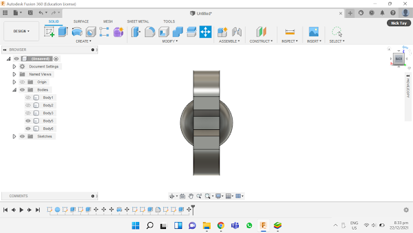
 Step 8: Extrude the circle outwards by 20 mm.
 Step 9: Using the "Fillet" function, round off one end of the cylinder.
 Step 10: Create another sketch. Draw a rectangle (20 mm by 40 mm) and fillet its corners by 10 mm.
 Step 11: Draw two circles that are 10 mm in diameter each.
 Step 12: Draw 3 lines to form a small trapezium at the central right side of the rectangle.
 Step 13: Using the "Trim" function, delete the excess line.
 Step 14: Extrude the new sketch outwards by 10 mm. This will form the main wind-up key of the Bob-Omb.


Step 21: Extrude the circle upwards by 30 mm. This will form the leg of the Bob-Omb. Step 22: This is what the figure should look like.
 Step 23: Using the "Fillet" function, round off the edges of the Bob-Omb's foot.
 Step 24: Using the "Move/Copy" tool, select the leg and foot of the Bob-Omb. Select "Translate" and click on "Create Copy". Drag the selected leg and foot to the right by 32.5 mm.
 Step 25: This is what the completed Bob-Omb looks like.
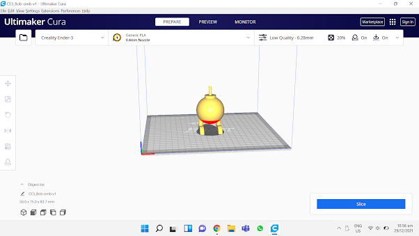 Step 26: Open Cura and upload the STL file. Ensure that supports and adhesions are turned on. If necessary, change the settings of the support and adhesion to suit your own needs. For my design, the Support Structure Type is "Tree" and the Build Plate Adhesion Type is "Brim".


For our first tutorial lesson in week 7, we learned more in-depth about 3D printing. We had previously gone through the basics of 3D printing in the previous semester.
Background Information
3D printing is a form of Additive Manufacturing (AM), where a physical object or part is created from a 3D digital model file by adding and laying down successive thin layers of material upon one another. 3D printing allows us to create objects that cannot be normally created using subtractive manufacturing.
Workflow in 3D Printing
1. Creating a printable 3D Design in Fusion 360
- Firstly, we have to create a 3D digital model file in a 3D modelling software. For example, Fusion 360 is a Computer-aided Drafting and Drawing (CADD) software that allows us to sketch and design physical components.
- These are the common input file types for 3D printers. This step can be done by exporting the 3D digital model file as any of the two file types in the 3D modelling software.
3. Slicing the 3D representable file (STL or 3MF) into layers using Cura slicer software
- Cura slicer is a software that is able to convert the saved STL file into layers, determine the print characteristic of each layer and convert the print characteristics of these layer into a language understandable by the 3D Printer (usually G-Code). The slicer software will usually have the configuration code for a particular set of 3D Printer(s), and is saved/transferred to the 3D Printer using a SDCard or thumbdrive.
4. Converting the layers into instructions for the 3D printer (G-Code)
- We can customise the other print settings (e.g. materials used, infill percentage, supports) according to the object's requirements.
- The object is printed layer-by-layer. Different technologies and materials control the thickness, surface finish, and durability of the finished object, while part size controls the print time.
3D Printing Techniques
The first technique, Fused Depositing Modelling (FDM), is the most commonly used and cheapest type of 3D printing.
The printing material is heated to near its melting point, and a nozzle extrudes it out in a way that traces the cross section of a part for each layer. This process repeats for each layer.
The technique's main advantage is that the printing process is quick, and requires inexpensive machines and materials. However, FDM has the lowest resolution and accuracy compared to other 3D printing techniques, thus they are not suitable for printing complex parts or parts with intricate features.
FDM is most commonly used in low-cost rapid prototyping and basic proof-of-concept models.
Figure 1: Fused Depositing Modelling (3D Printing Industry, no date)
The second technique, Stereolithography (SLA), can be considered the first 3D printing process, invented in the 1980s.
SLA utilize an ultraviolet laser to selectively cure a layer of liquid curable photopolymer resin, which is then pulled up and reset for the next layer. For each layer, the laser beam traces a cross-section of the part pattern on the surface of the liquid resin. Exposure to the ultraviolet laser light cures and solidifies the pattern traced on the resin and fuses it to the layer below.
SLA has the one of the greatest versatilities out of all 3D printing techniques. SLA parts also have the highest resolution and accuracy, the clearest details, and the smoothest surface finish of all plastic 3D printing technologies. However, parts printed using SLA are sensitive to long exposure to UV light.
SLA is widely used in a range of industries from engineering and product design to manufacturing, dentistry, jewelry, model making, and education.
Figure 2: Stereolithography (3D Printing Industry, no date)
The last technique, Selective Laser Sintering (SLS), is the most common additive manufacturing technology for industrial applications due to its ability to produce strong, functional parts.
SLS uses a high power laser to fuse small particles of polymer powder into a mass that has the desired three dimensional shape. The laser selectively fuses powder by scanning the cross-sections on the surface of a powder bed. After each cross-section is scanned, the powder bed is lowered by one layer thickness. A new layer of material is applied on top and the process is repeated until the object is completed. The unfused powder supports the parts during printing and eliminates the need for dedicated support structures.
Parts produced with SLS printing have excellent mechanical characteristics, with strength resembling that of injection-molded parts. However, parts produced using SLS have a rough surface finish, and the material selection for SLS 3D printing is limited.
SLS is most commonly used in industries that need only a small quantity of objects printed in high quality materials, such as the aerospace industry, in which SLS is used to build prototypes for airplane parts.
Figure 3: Selective Laser Sintering (3D Printing Industry, no date)
Common 3D Printing Materials
Common materials used for 3D printing are usually thermoplastics.
Acrylonitrile butadiene styrene (ABS) is one of the most commonly used materials for 3D printing. This is due to its durability. On top of that, it also has a high machinability rating and strong electrical insulation capabilities. However, it has a relatively low melting point, as well as poor solvent, fatigue and UV resistance. It is most commonly used for models, prototypes, patterns, tools and end-use parts in the automotive industry, machine prototype construction. It is also used to make pipes and fittings.
Polylactic acid (PLA) is a highly versatile material. Its main selling points are its low cost due to being made from renewable sources, and its biodegradability due to being made from natural sources. It is also easy to use, do not tend to warp and have good reusability. However, it has low heat resistance due to its low melting point, and can be brittle due to its low tensile strength. It is used to make food containers, cutlery and laminations.
Polyethylene terephthalate glycol (PETG) is another commonly used material for 3D printing. Its main strength is their durability. It is also chemically resistant and flexible. However, it is not UV-resistant, and weaken considerably from exposure to UV light. It is also sensitive to moisture and humidity, due to their hydroscopic properties. It is mostly used to make food and drinks containers, mechanical components and machine guards.
Polycarbonate-ISO (PC-ISO) is an industrial thermoplastic. It is a biomaterial, meaning it is biocompatible, allowing it to be used in a wide range of medical applications. It is also easily sterilisable, strong, durable and heat resistant. However, the supports used for it during 3D printing have to be broken away and removed by hand, which may cause damage to more intricate areas of the part's design. It is most often used to make food and drug packaging, and medical devices.
Uses of 3D Printing
Automotive: 3D printing is commonly used to produce manufacturing aids such as jigs and fixtures, as traditionally making these manufacturing aids require a lot of time and money, and are generally less efficient than 3D printing processes. 3D printing is also used to make replacement parts of older models of vehicle that are no longer in production.
Construction/Architecture: Architectural models can be 3D printed to provide accurate demonstration models of an architect’s vision. It offers a relatively fast, easy and economically viable method of producing detailed models directly. Alternatively, 3D printed buildings can be created by first creating modular pieces of the building, then shipping them to the location and assembling them onsite.
Healthcare: Bioprinting is a form of 3D printing where living cells are layered upon one another to form living tissue, which can then be used to make functional organs. These 3D printed organs can then be inserted into the human body for use without any adverse effect. 3D printing also allows for easy customisation of dental products such as braces and dentures, based on patient X-ray and CT images to suit the patient's unique dental anatomy.
Prototyping: Prototypes of commercial products can be 3D printed first to allow for a physical evaluation of the design. It allows for functional testing to be performed before committing to a full production run to identify mistakes and rectify errors, ensuring that the final product is suitable for release to the market to consumers.
The figure below summarises the different types of 3D printers available in SP's laboratories, as well as their different specifications.
Figure 4: Summary of 3D Printers
3D Printer Characteristics/Slicer Settings
Some common characteristics of the 3D printer can be tweaked to help us in the tuning of the software parameters, allowing us to have finer prints, faster prints or stronger prints.
Layer Height (extruded filament thickness) refers to the height of each layer of the print. It affects the resolution, speed and smoothness of the print. The smaller the layer height, the more layers will be required in the overall print. This means that the printer will have more room to generate finite detail on parts like miniatures. However, having more layers also means longer print times and weaker parts. For a typical 0.4 mm nozzle, the typical layer height is 0.2 mm, with a range from 0.1~0.4 mm.
Wall Thickness controls the number of strands required for the thickness of the wall. It will affect the print time and the strength of the print. For example, if the layer height = 0.2 mm, then a wall thickness of 1 mm will require 5 strands laid side-by-side. The typical wall thickness is minimum 0.8 mm.
Infill Percentages is the internal filling in 3D printed parts. It controls the amount of fill in the internal cavities of prints. Infill allows for better control over the strength, weight, material consumption, and internal structure of a part without having to adjust its appearance or external features. More robust infill patterns and larger infill densities will extend printing times and consume more materials, but increase a part’s strength and weight. There are many infill patterns to choose from, each with its own design and characteristics.
Bridging and Overhangs refers to the prints between 2 points that have no connection to each other. Normally, a 3D printer first prints the base layer, on which it builds up layer by layer. In contrast, there is no base layer between two points when bridging. Consequently, printing must be done in the air so that the gap can be bridged. There is a limit before the print fails and sagging strands appear. You need to test for the maximum distance for each printer. It affects the quality of the print. Most printers can handle an overhang of 45 degrees.
Supports are slicer-generated are structures that hold up overhanging features on models. They make impossible prints possible by allowing overhangs to be printed. Supports are removed after the print is complete. They add to the print time as well as the touch-up and finishing time to the model. Orientation of the model helps in the determining of supports.
Bed Adhesion is a physical feature added to a print. It is auto-generated by the slicer when instructed to do so and is designed to enhance bed adhesion.
- A skirt is a distant and detached perimeter that outlines a print.
- A brim is a set of lines attached to the outside of a print’s first layer, sprawling from its base.
- A raft is a complete base upon which the model grows.
Object orientation can improve the adhesion and limit the use of supports. By using the "Rotate" feature to change the orientation, we can orientate the object in a way such that supports are not required. By using the "Place on bed" feature, we can ensure proper placement of the object on the print bed.
Individual Activity
For this activity, we were required to design in Fusion360 and 3D print an object that could not be easily made subtractively. The object should be small in size should require no more than 1 hour of printing.
I decided to print a Bob-Omb from the Super Mario franchise.
Figure 5: Bob-Omb
Step 1: Create a sphere that is 50 mm in diameter.Step 2: From the base of the sphere, create a new sketch. Draw a circle that is 20 mm in diameter.Step 5: Extrude the new circle such that it slightly protrudes out of the fuse. The protrusion will form the fuse. Ensure that "New Body" is selected when extruding the part.
Step 15: Using the "Move/Copy" function, drag the wind-up key to the connector, and ensure that it is centralised.
Step 16: This is what the figure should look like.
Step 17: Using the "Move/Copy" function, drag the completed wind-up key to the main body, and ensure that it is centralised.
Step 18: Create a new sketch. Using the "Line" function, draw a line that is 40 mm long. Using the "Fit Point Spline" function, place down several points in the general shape of the Bob-Omb's foot. Use the "Select" tool to drag and reposition points. If necessary, delete a few points.
Step 19: Extrude the sketch outwards by 7.5 mm.
Step 20: Create a new sketch. At the lowest point of the curve, draw a circle that is 7.5 mm in diameter.
Step 21: Extrude the circle upwards by 30 mm. This will form the leg of the Bob-Omb.
Step 27: Slice the design into layers. Take note of the time required to print the design. For my design, since the time required to print it was more than 1 hour, I had to scale it down to 47% of its original size so that it could be printed fully within an hour.
Below is the STL file of my design.
Bom Bom Bakudan
Here is the link to download the STL file: https://drive.google.com/file/d/1nVrgSUbHNGvrTl_JHh_BZqvZNp3Al8Dw/view?usp=sharing
Why It Could Not Be Made Subtractively
The main body of the Bob-Omb is a sphere, which can be made subtractively, but the design also contains a wind-up key, legs and fuse. These parts are very delicate and cannot be achieved by subtractive manufacturing easily.
3D Printing Process Documentation
Figure 6: 3D Printing Process (10%)
Figure 7: 3D Printing Process (50%)
Figure 8: 3D Printing Process (90%)
Figure 9: Completed Bob-Omb Design
Figure 10: I Accidentally Broke Off The Legs While Removing The Supports :/
Figure 11: Hero Shot
Reflection
In conclusion, this 3D printing exercise was interesting and very fun to carry out. Initially, I had thought that the 3D printing process would be very complex and would require very detailed steps to use it. However, all I really needed to do was to upload my completed design file into the hard drive containing the SD card, insert the SD card containing the design file into the 3D printer and key in a few inputs to start the 3D printing process. Overall, I think that this activity was a good learning experience. In my free time, I will fix the legs of the Bob-Omb and have it painted so that it will look good as a display piece on my study table. I may also practice making more 3D models in Fusion 360 and have them printed out for display purposes.
References
3D Printing Industry. n.d. The Free Beginner's Guide - 3D Printing Industry. [online] Available at: <https://3dprintingindustry.com/3d-printing-basics-free-beginners-guide/> [Accessed 29 December 2021].
3D Printing. n.d. What is 3D Printing?. [online] Available at: <https://3dprinting.com/what-is-3d-printing/> [Accessed 29 December 2021].
Blog.spatial.com. 2020. Applications of 3D Printing in the Medical Field. [online] Available at: <https://blog.spatial.com/the-future-of-3d-printing-in-the-medical-field> [Accessed 29 December 2021].
Keane, P., 2021. Building to get Freeform 3D Printed Composite Facade. [online] 3D Printing. Available at: <https://3dprinting.com/construction/building-to-get-freeform-3d-printed-composite-facade/> [Accessed 29 December 2021].
Markforged. n.d. 3D Printing Basics. [online] Available at: <https://markforged.com/resources/learn/3d-printing-basics> [Accessed 29 December 2021].
Naramore, C., 2020. How 3D Printing Is Changing Auto Manufacturing. [online] 3D Printing. Available at: <https://3dprinting.com/automotive/how-3d-printing-is-changing-auto-manufacturing/> [Accessed 29 December 2021].
Nawrat, A., 2020. 3D printing in the medical field: four major applications revolutionising the industry - Verdict Medical Devices. [online] Medicaldevice-network.com. Available at: <https://www.medicaldevice-network.com/features/3d-printing-in-the-medical-field-applications/> [Accessed 29 December 2021].


Comments
Post a Comment